

LapAR Pro Setup (1st Generation)
Assemble the 1st-Generation LapAR Pro trolley system and monitor.
Welcome to the step-by-step assembly guide for the LapAR Pro. Whether you prefer step by step instructions or a video demonstration, this guide will walk you through the assembly process.
Before you begin, take a moment to review the package's contents and acquaint yourself with the included components. The following content has been crafted to provide you with all the insights required to transform individual parts into a functional and invaluable tool for honing your surgical skills.
Step 1
When opening your simulator it is recommended that you unpack all package contents and arrange them before starting construction.
Step 2
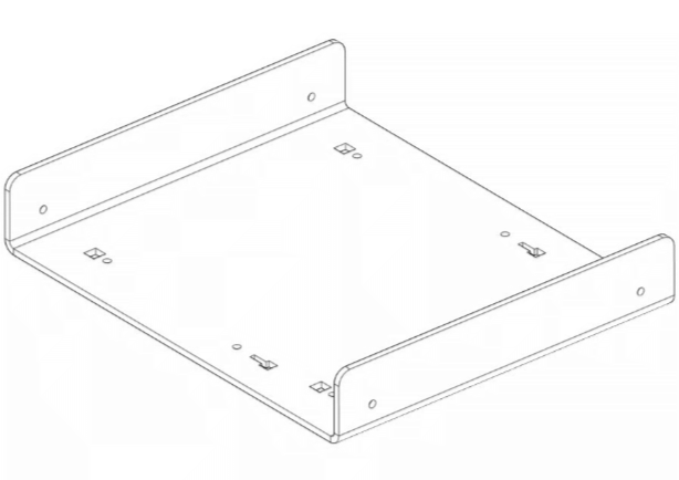
Now take the following parts:
Step 3
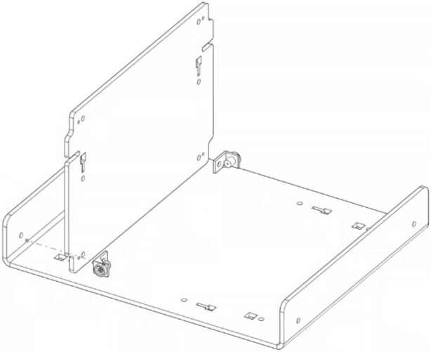
Screw into place 2x MA01 using 2x M5B24 and 2x WN14
Step 4
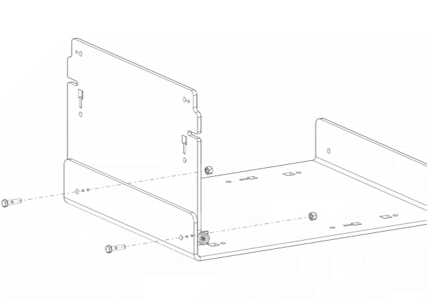
Repeat the last two steps with the same parts on the front panel AR20_U01 as shown in the image.
Step 5
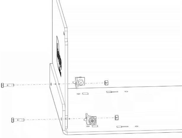
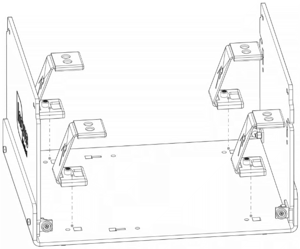
Take 4x AR20_M-BKT, position them in the keys provided.
Step 6
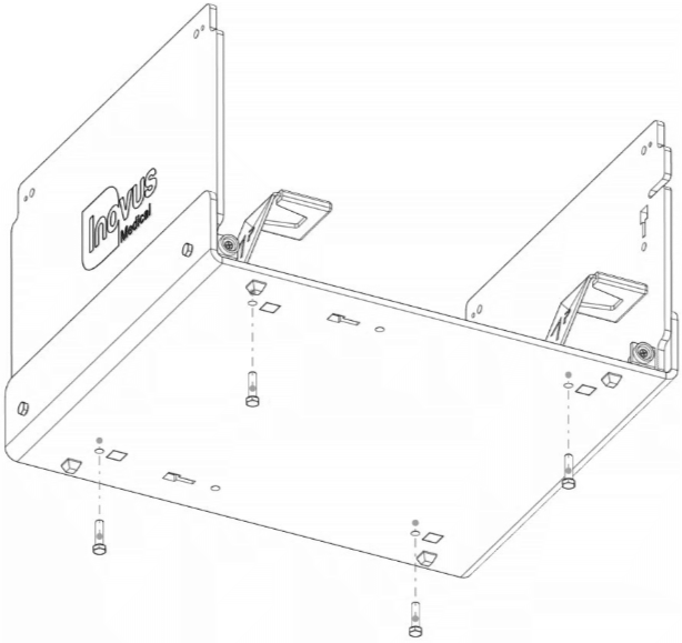
Using 4x M5B24 screw each AR20_M-BKT into position on the base.
Step 7
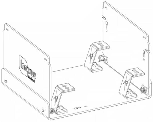
At this stage the simulator should look exactly like the reference image.
Step 8
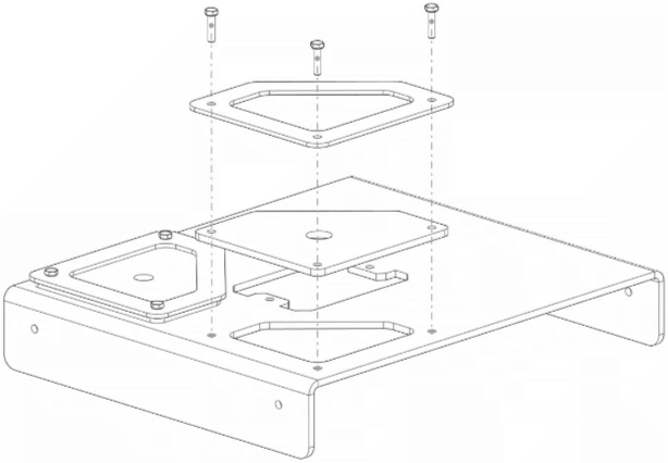
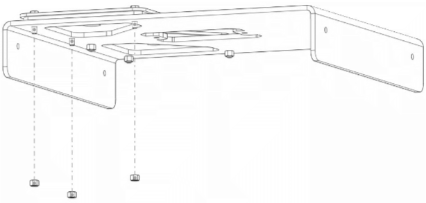
Locate the following parts:
Step 9
Now attach 3x WN14 to the bolts coming through the bottom surface.
Step 10
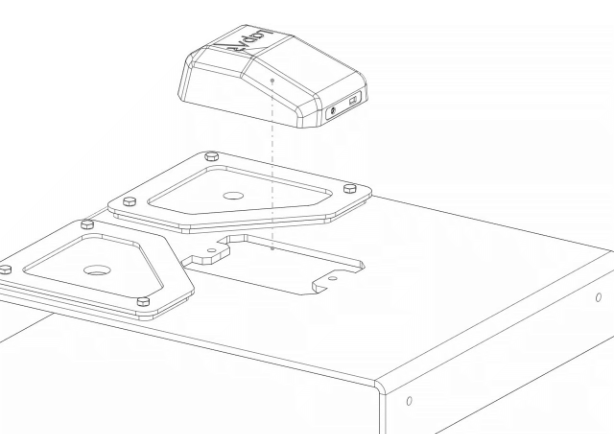
Remove the AR20_CAM from its packaging and place into position as shown.
Step 11
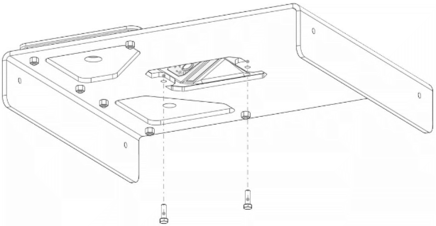
Take 2x M5B24 bolts and affix the AR20_CAM into position.
Step 12
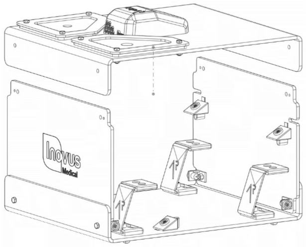
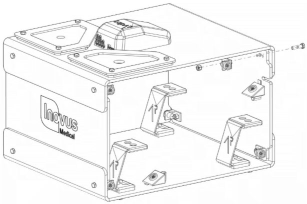
Take the sub-assembly from the last four steps and place it over the upright panel of the simulator as shown.
Step 13
Locate the following parts:
Step 14
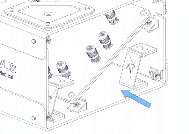
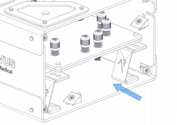
It is important to note that the simulator is capable of multiple platform positions.
Step 15
You will use the flat platform for LapPass® and any other non-AR tasks.
Step 16
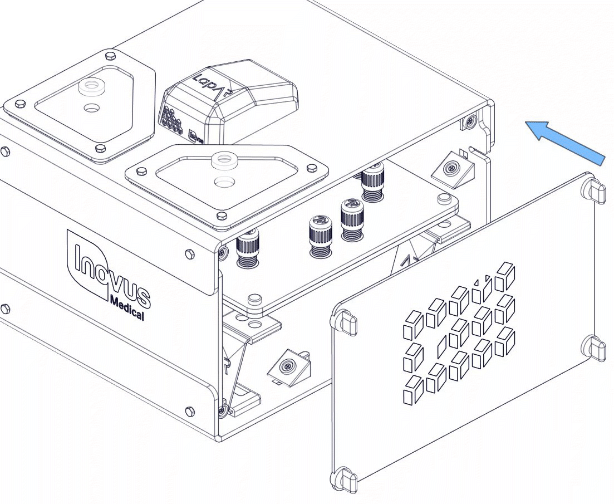
Snap into place both side panels and move on.
Step 17
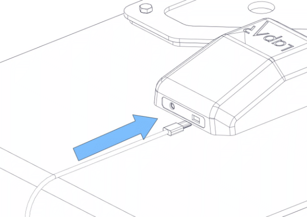
Connect the USB micro into the back of the camera.
Step 18
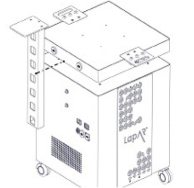
Start the assembly of your portable trolley system by unscrewing the M8 bolts at the rear of chassis so that you have around 3-4mm of space between the head of the bolt and the chassis wall.
Step 19
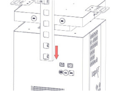
Drop the bracket onto the bolts.
Step 20
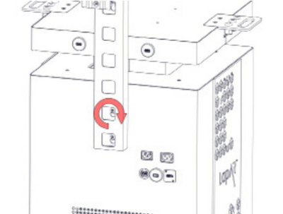
Screw the bolts tight using the Allen key provided.
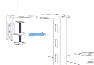
Step 21
Take the assembled monitor bracket and clamp it in position as shown.
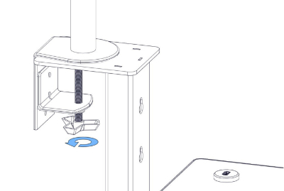
Step 22
Screw the clamp until tight.
Step 23
Attach the monitor screen using the 4x M4 bolts provided.

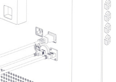
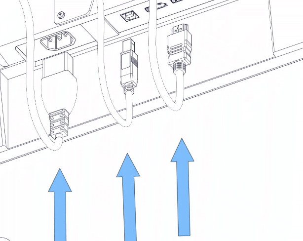
Step 24
As shown in the image, plug in the IEC, HDMI & USB cables.
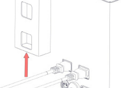
Step 25
Carefully thread the 3 wires we plugged in during the previous step up through the L-shaped bracket and onto the monitor bracket.
Step 26
Position the wires as such and plug in to the appropriate socket.
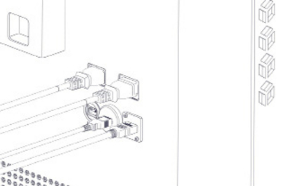
Step 27
Plug the IEC connector into the back of the system.
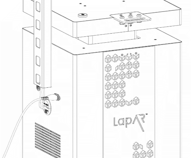
Step 28
Plug the connector into the mains power.
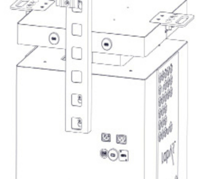
Step 29
If a Wi-Fi connection isn't present, plug in the network cable provided with the system.
Step 30
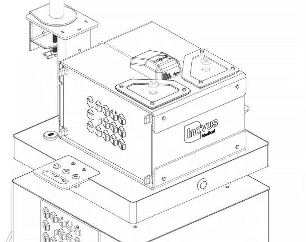
Place your constructed simulator that you should have already assembled onto the top surface.
Step 31
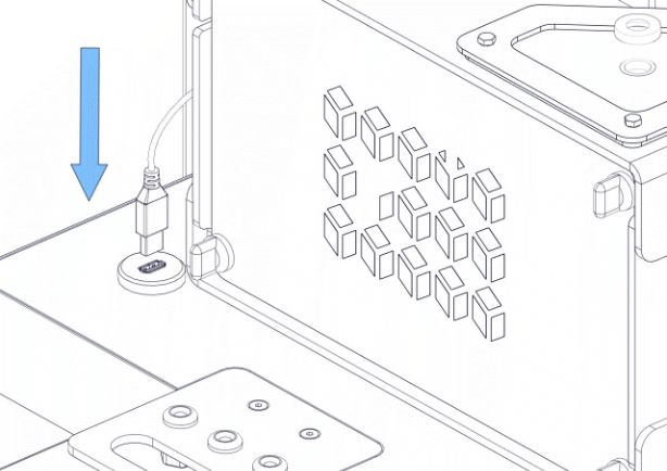
Plug in the USB cable to the USB ports on the trolley system.
Step 32
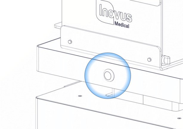
Turn the system on using the power switch on the front. Once the computer has loaded up, select the LapAR(TM) icon on the desktop and follow the instructions inside the software.
Related articles
Community Discussions (0)
Real-world experiences from other users around this article.
Did this solve your problem?