

Bozzini Laparoscopic Simulator Setup Manual
Assemble the Bozzini Laparoscopic Simulator, monitor bracket, and light source.
Welcome to the step-by-step assembly guide for the Bozzini Laparoscopic Simulator. Whether you prefer step-by-step instructions or a video demonstration, this guide will walk you through the assembly process.
Before you begin, take a moment to review the package's contents and acquaint yourself with the included components. The following content has been crafted to provide you with all the insights required to transform individual parts into a functional and invaluable tool for honing your surgical skills.
Step 1
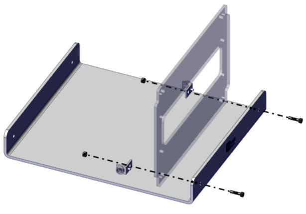
Construct the front panel section of the simulator.
Step 2
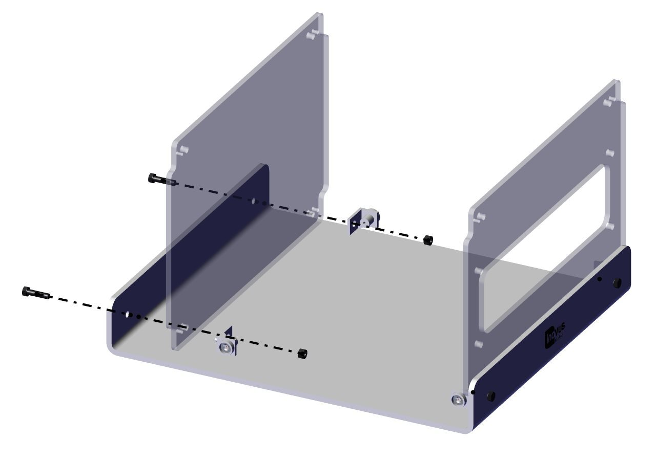
Repeat Step 1 for the rear panel 00000940.
Step 3
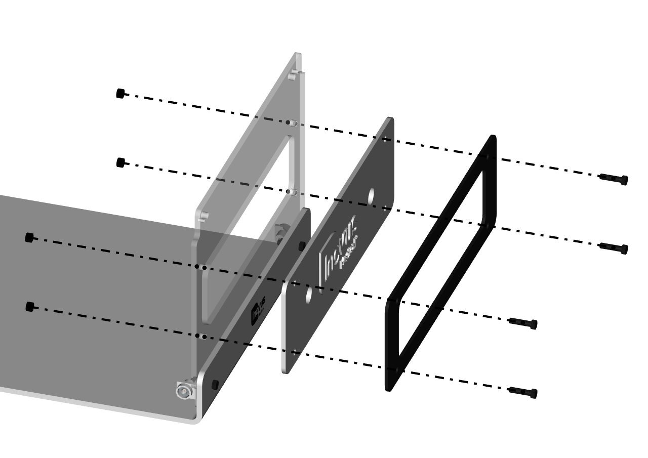
You will now need the following parts:
Step 4
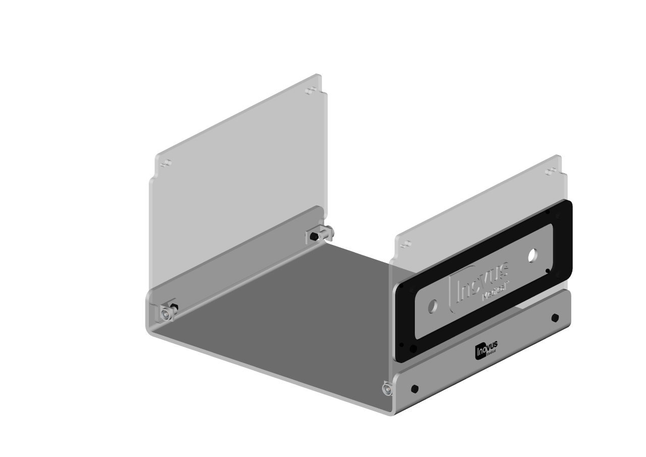
Your simulator should now look like this, with both upright panels securely in position.
Step 5
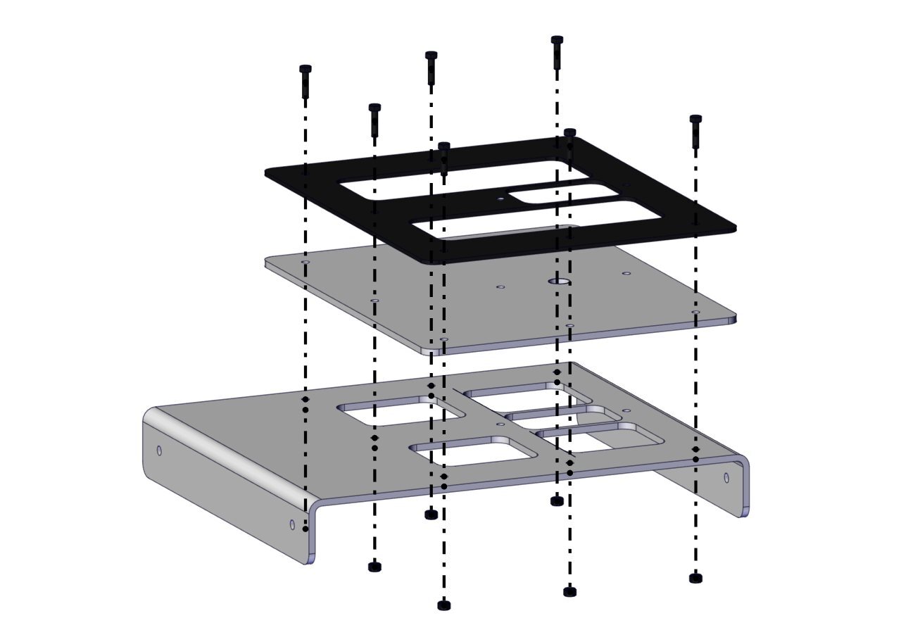
You may now start the top panel sub-assembly.
Step 6
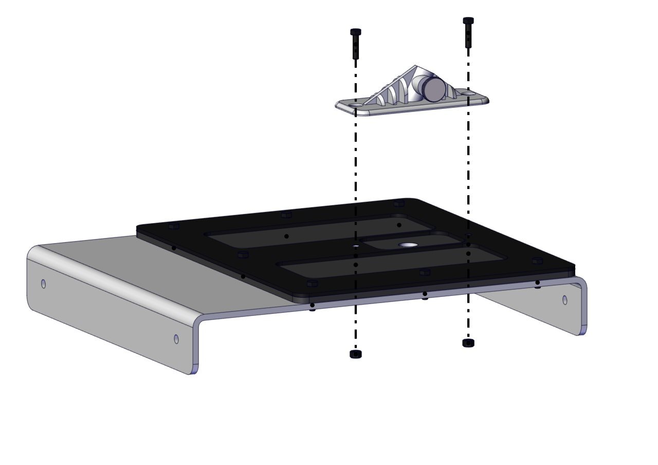
Isolate the scope bracket (00001280). Using 2 x 00000640 bolts and 2 x 00001159 nuts, secure the bracket as shown in the image.
Step 7
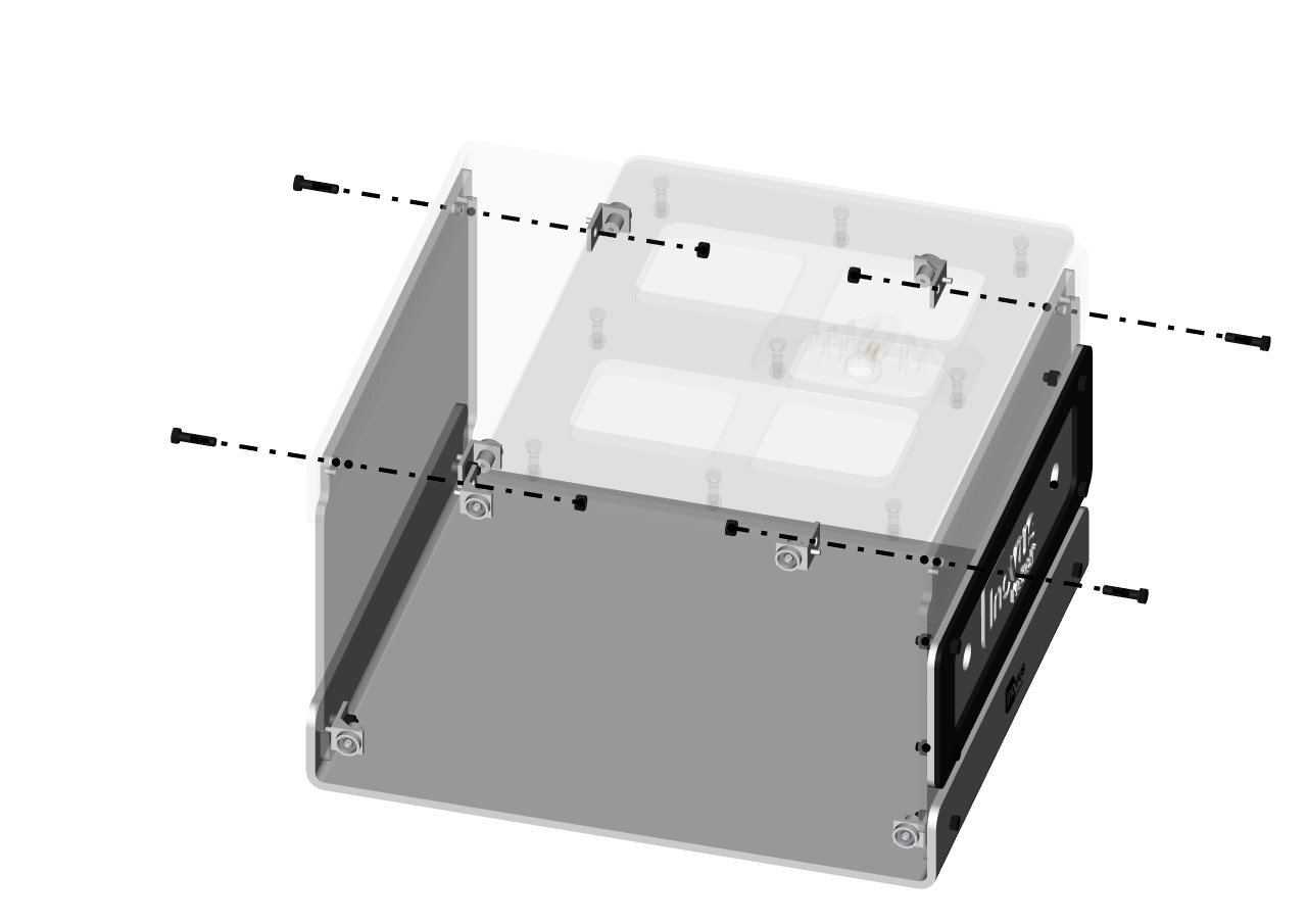
As in Steps 1 and 2, secure the top panel sub-assembly to the upright panels using:
Step 8
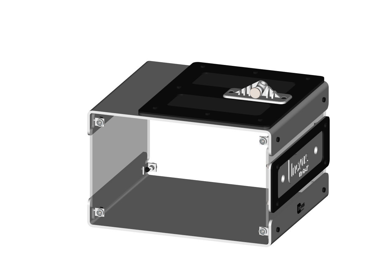
Your simulator should now look exactly like the image shown.
Step 9
You may now start the side panel sub-assemblies. Taking 00000946, 00000640 and 00000929, secure as shown using 4 x 00000640 bolts and 4 x 00001159 nuts.
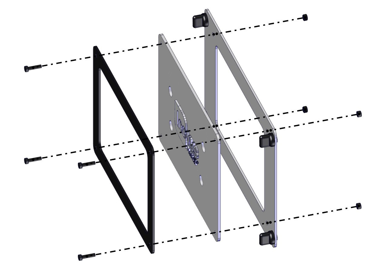
Step 10
Your side panel should look like this. Repeat the process one more time for the opposite side.
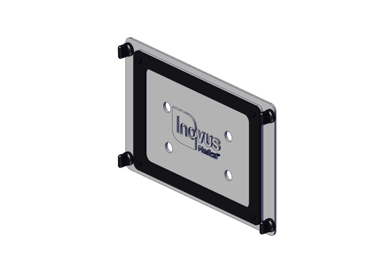
Step 11
Insert the 10 dummy trocars as directed in the image.
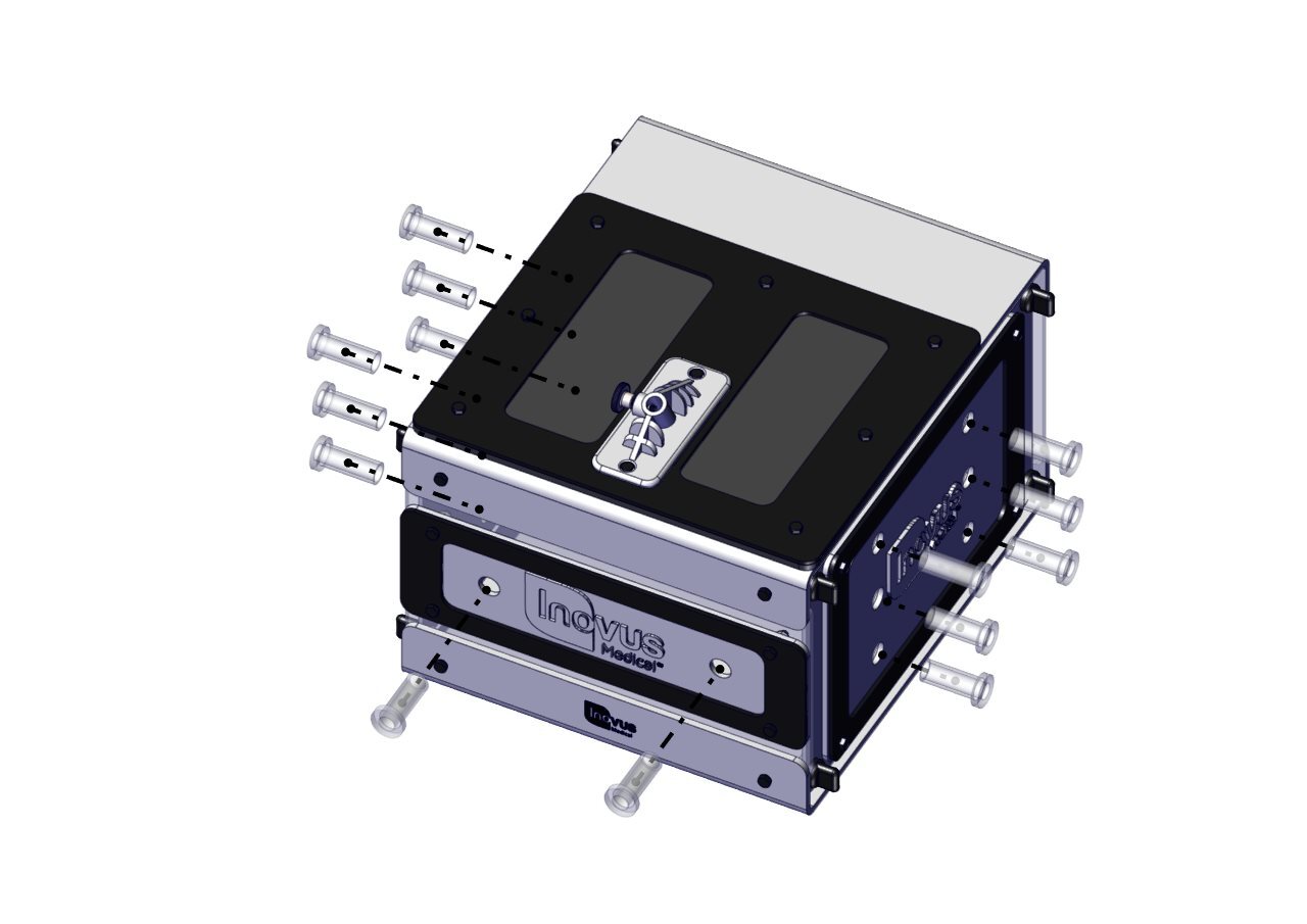
Step 12
You are now ready to assemble the monitor bracket. Begin by removing the C-clamp from the package.
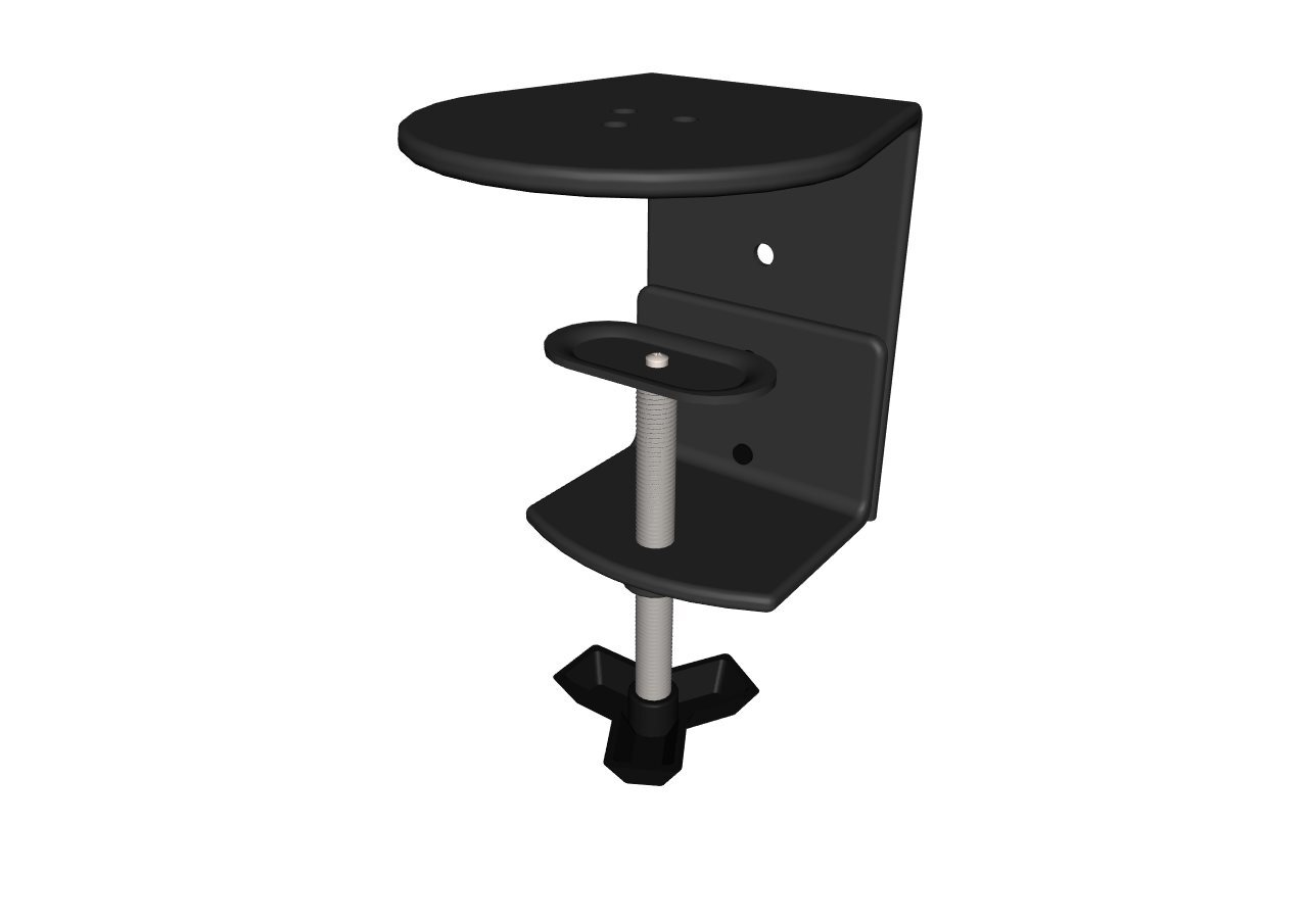
Step 13
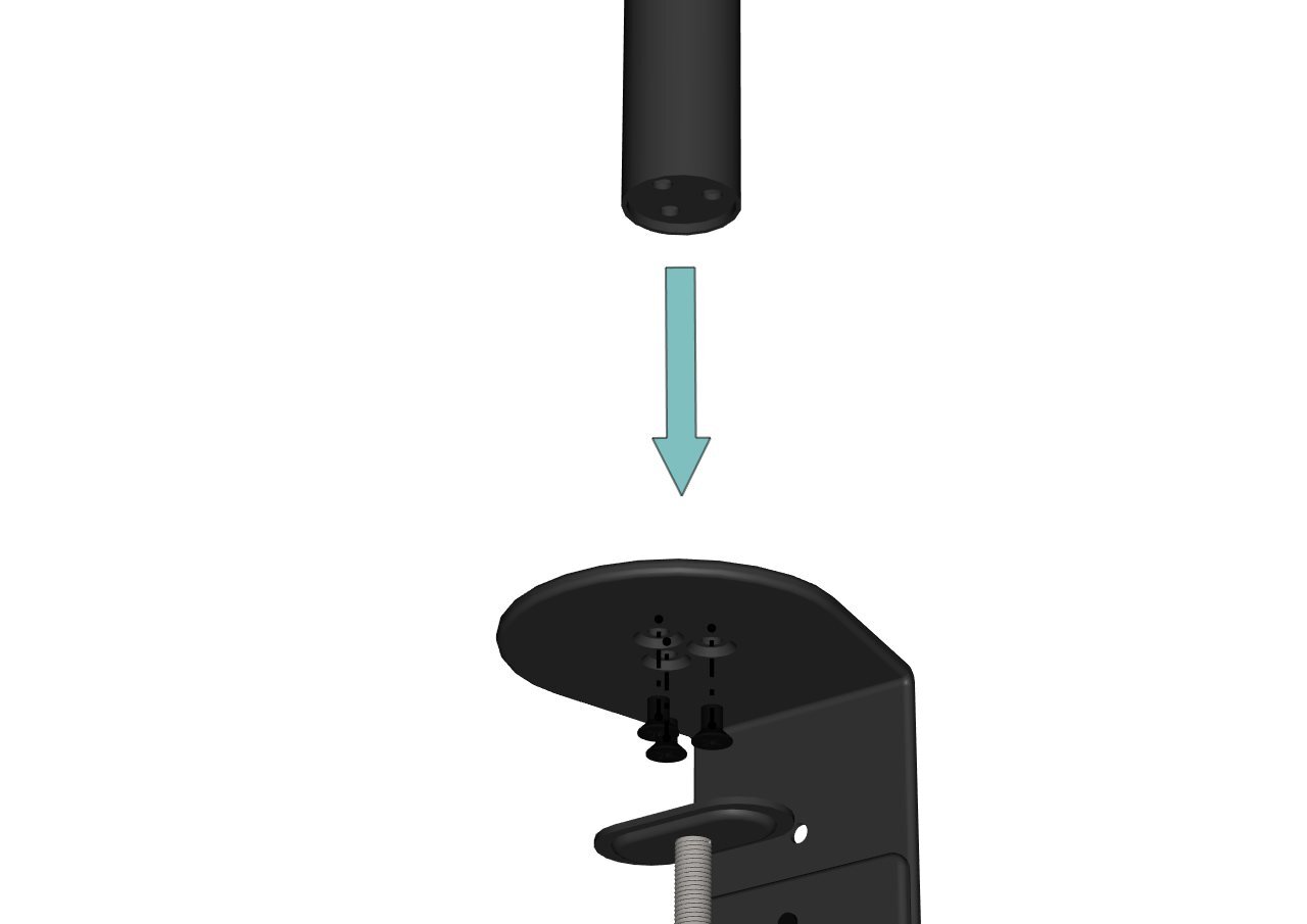
Using the three black bolts provided, attach the black post to the C-clamp.
Step 14
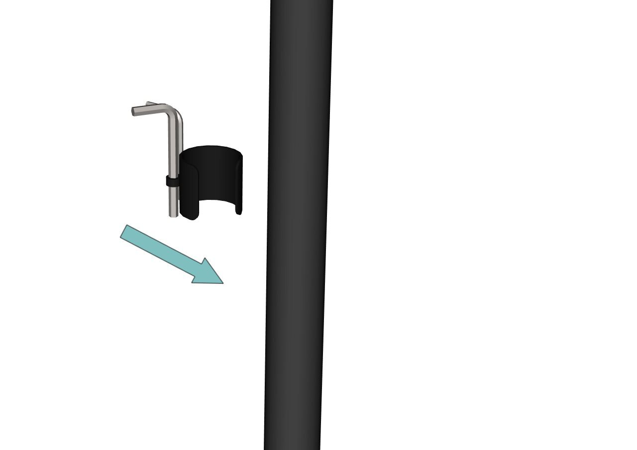
Just so that we know where they are for later, identify the two Allen keys along with the push fit clamp provided. Snap this to the post and move to the next step.
Step 15
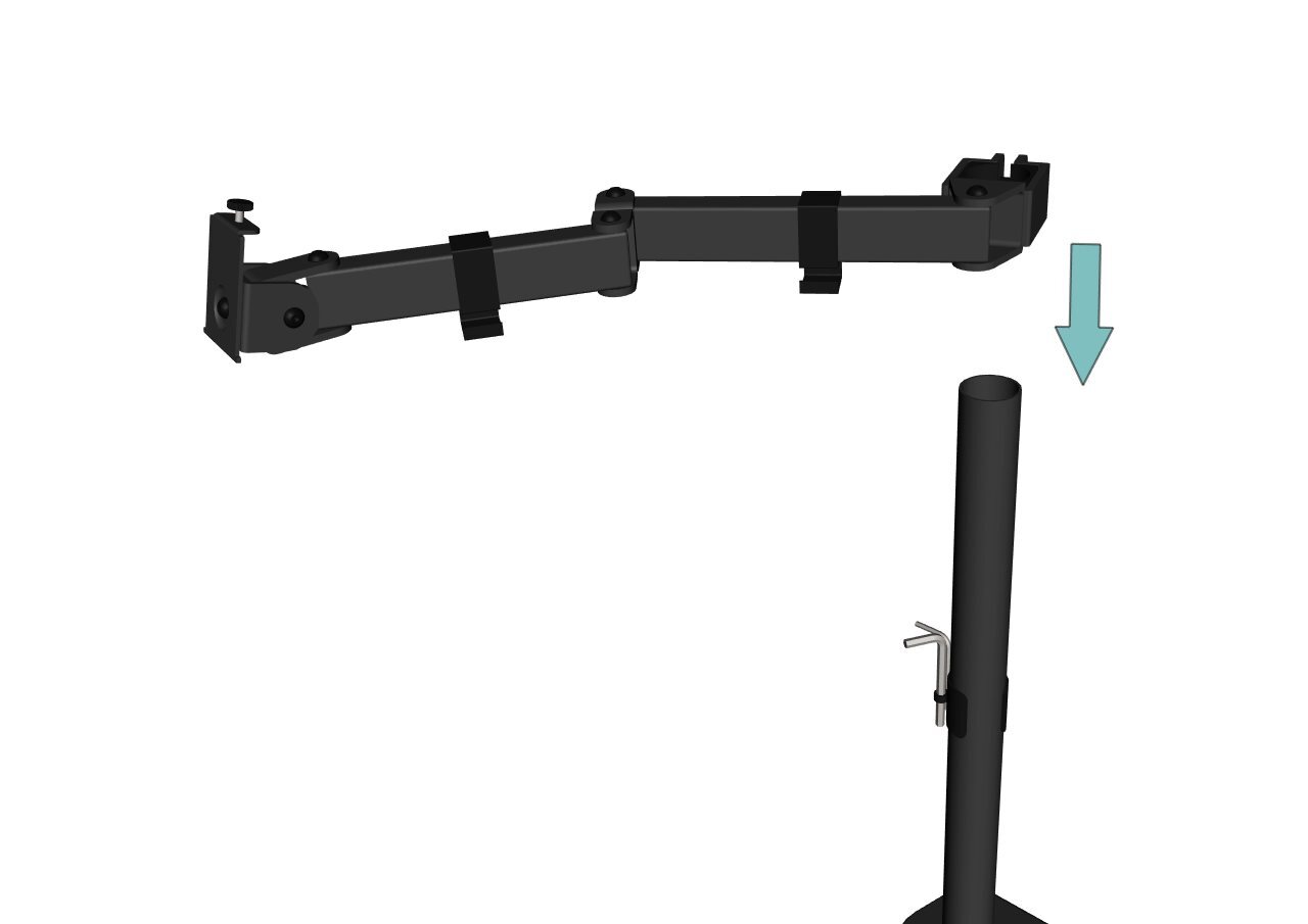
The swivel arm should be pre-assembled. Slide this onto the black post, then move to the next step.
Step 16
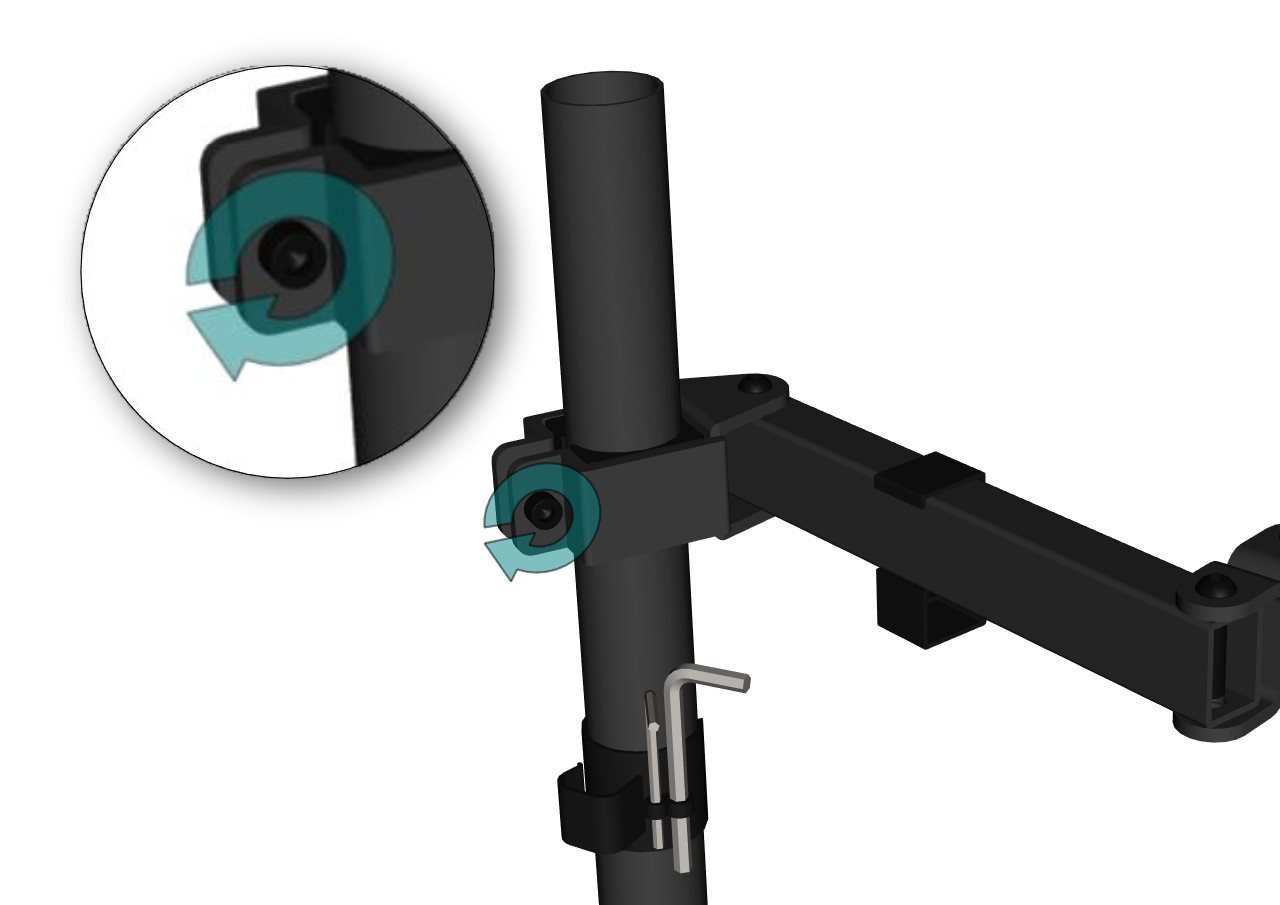
At the desired height, use the largest Allen key to lock into position by turning the bolt in a clockwise direction.
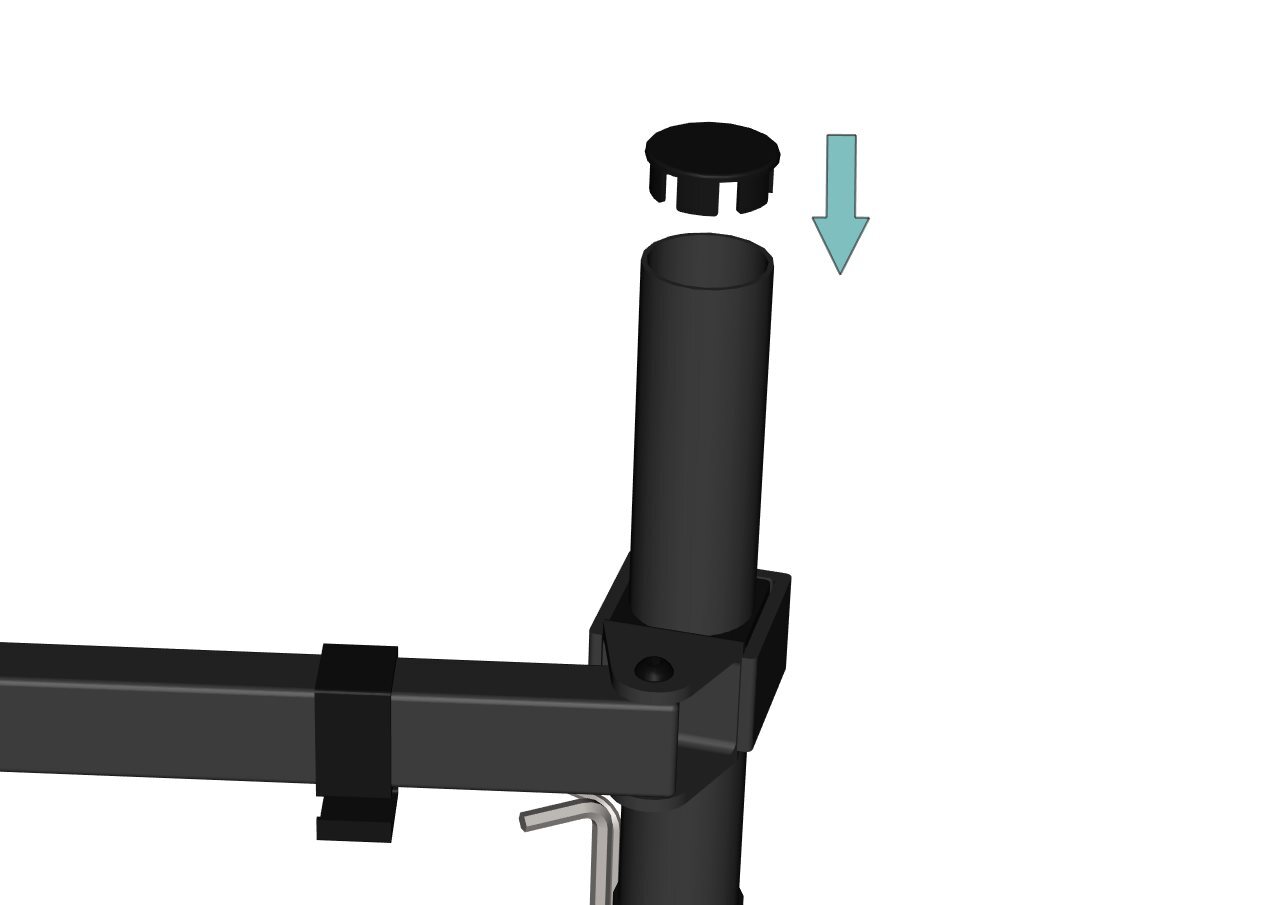
Step 17
Push the end cap into position.
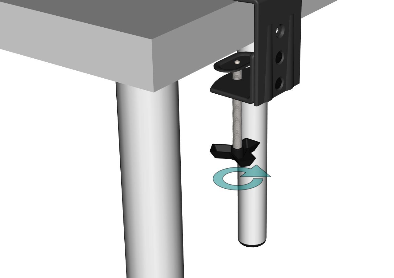
Step 18
With the bracket fully assembled, anchor it to your chosen work surface by turning the handle until it is tight.
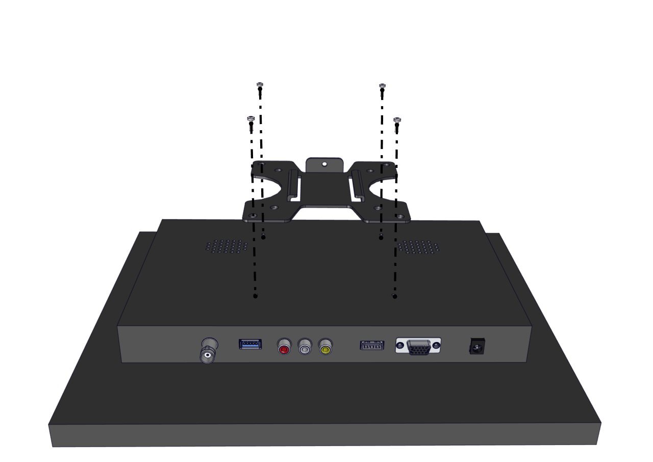
Step 19
Take the screen bracket and screw this to the back of the monitor using the bolts provided.
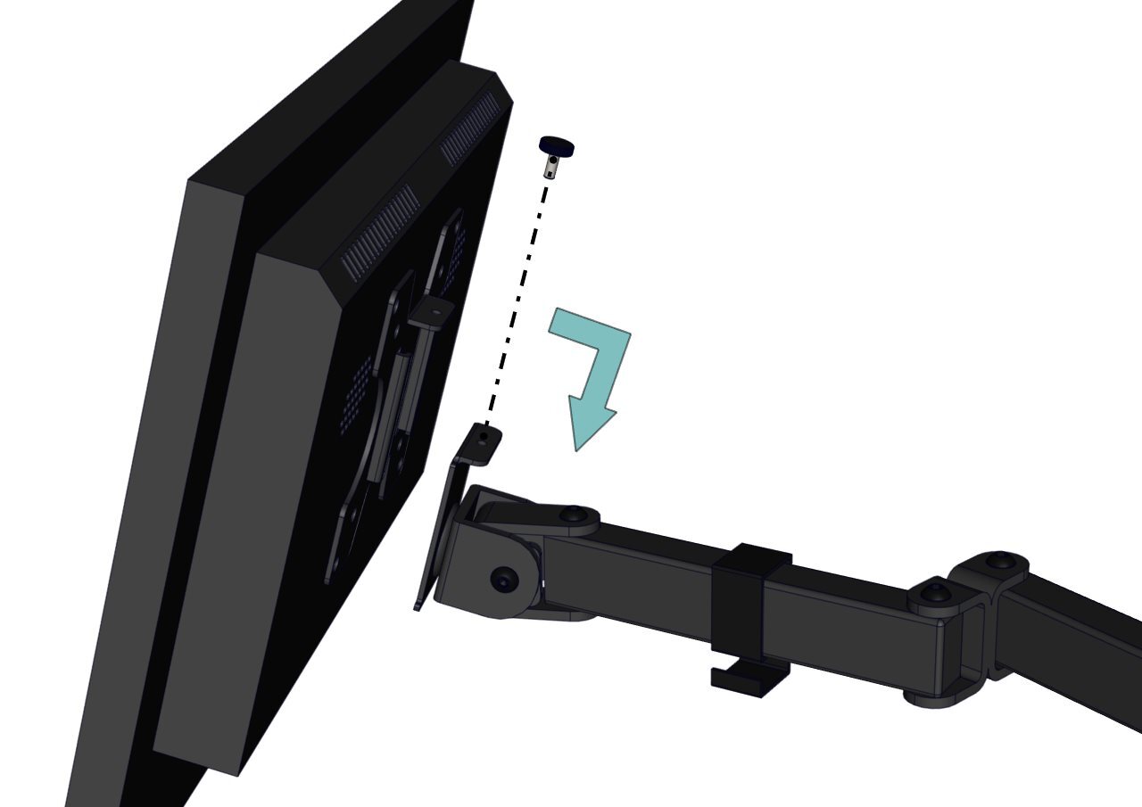
Step 20
Slide the monitor into position and screw the bolt into place.
Step 21
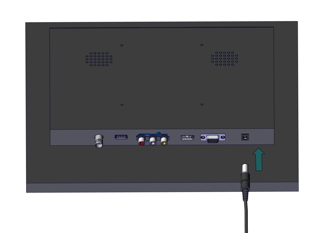
All wiring can be completed using the numbered stickers attached to the ends of each adapter. For additional support, use this visual guide.
Step 22
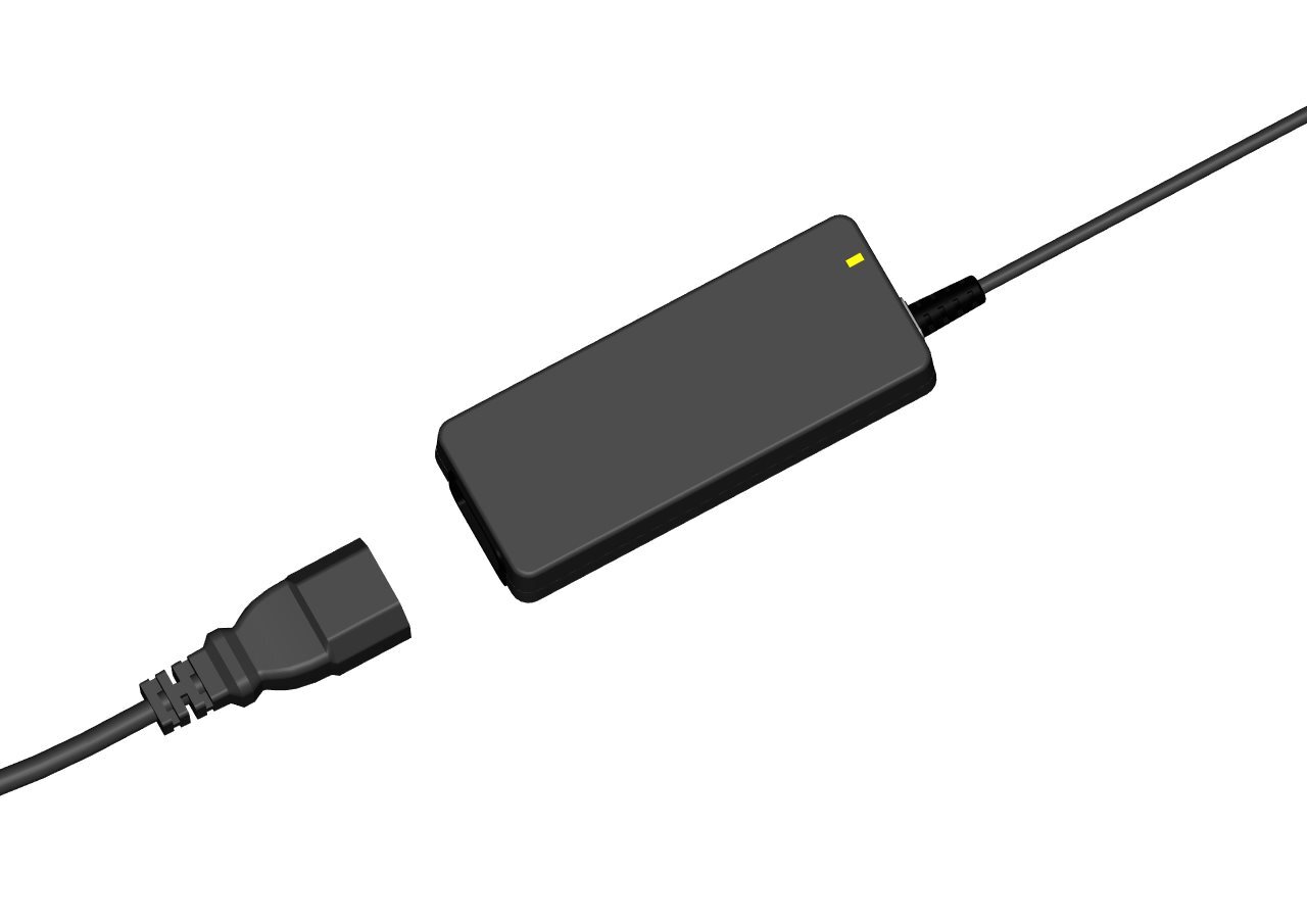
Plug the socket into the wall and then connect the IEC cable to the power adapter. When switched on, a green light may be shown.
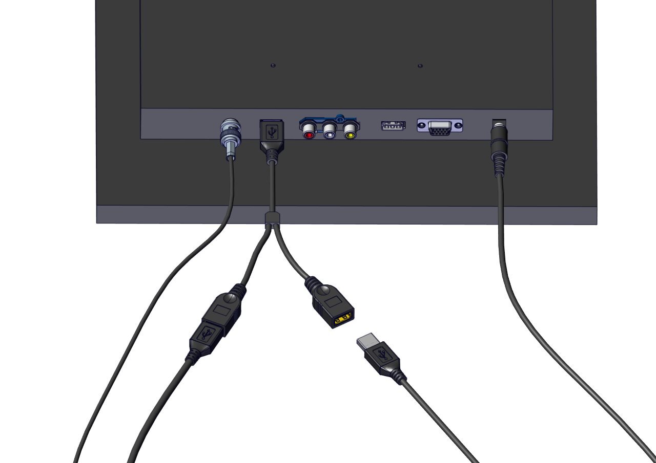
Step 23
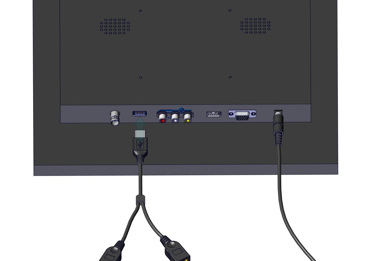
Connect the USB splitter to the rear of the monitor as shown.
Step 24
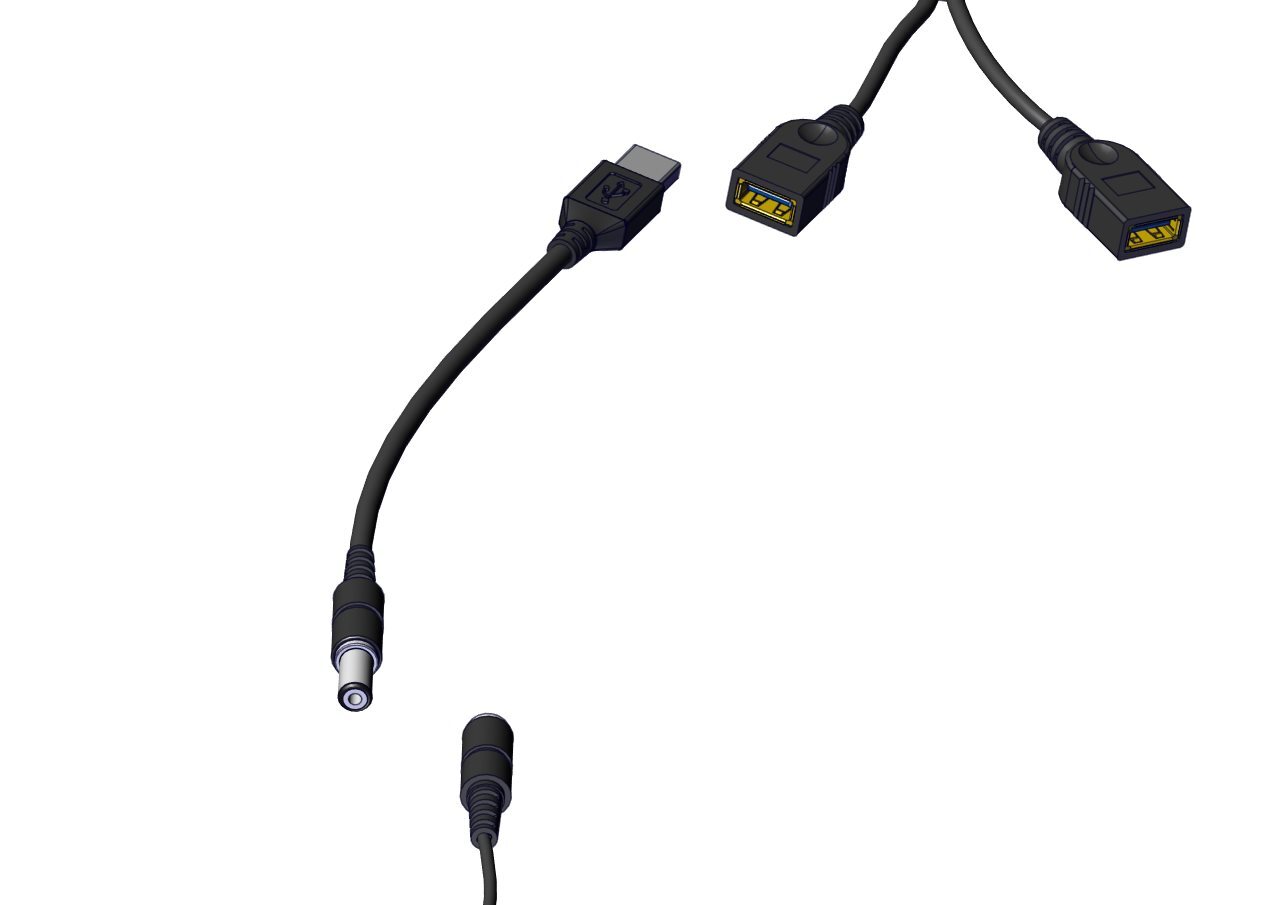
Connect the USB to 5V adapter to one of the USB ports. Connect the female end of the BNC cable to the male end of the 5V adapter.
Step 25
Connect the female end of the BNC extender to the screen.
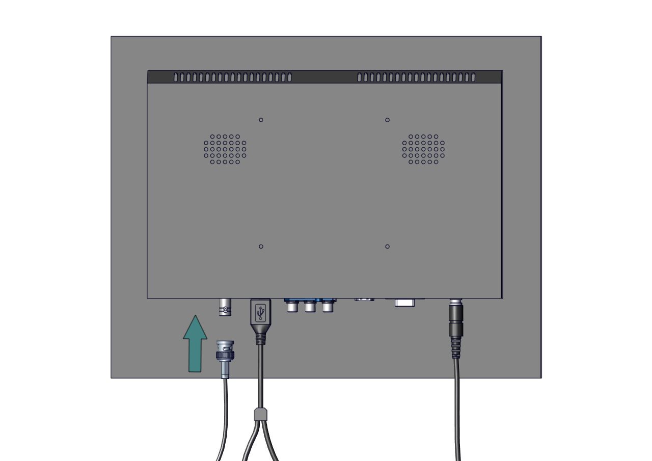
Step 26
Locate the endoscopic camera in the package. Connect the opposing ends of the BNC cable to the camera connectors.
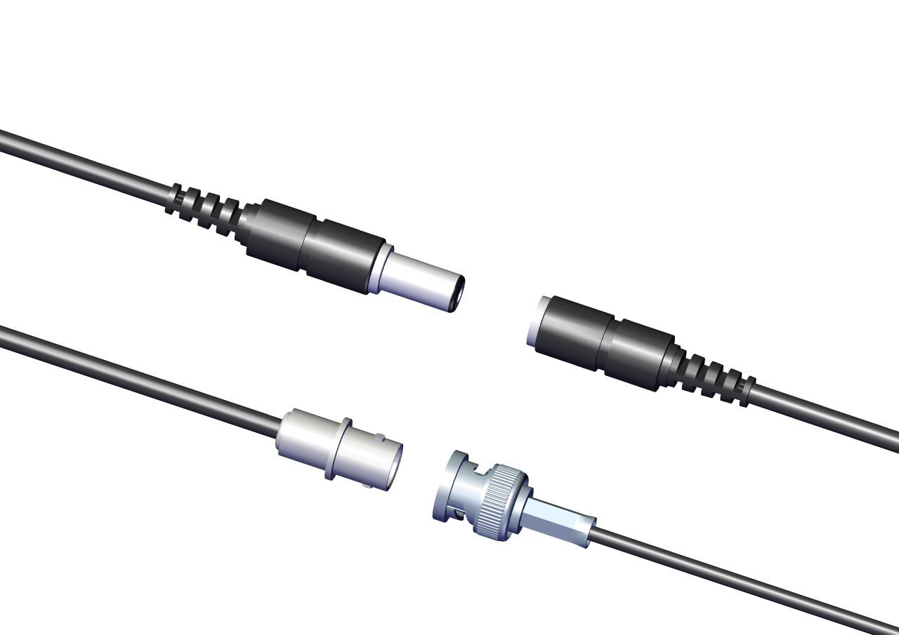
Step 27
Connect the USBA/B cable to the remaining USB port on the USB splitter.
Step 28
Now connect this wire to the Bozzini light source.
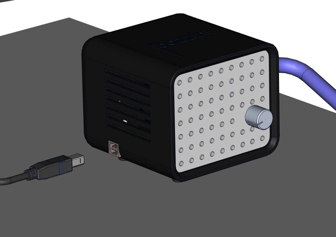
Step 29
Plug in the male end of the fibre optic cable into the light source.
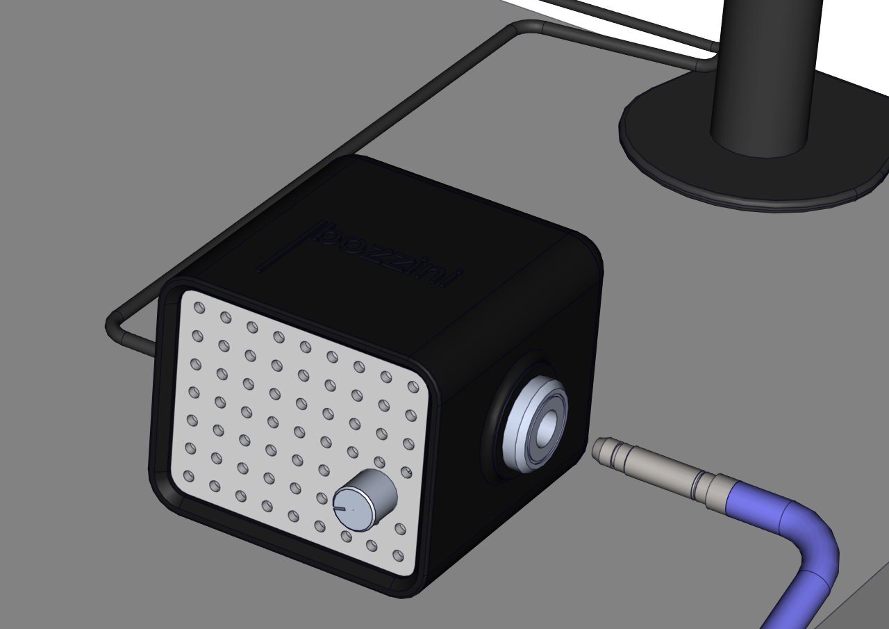
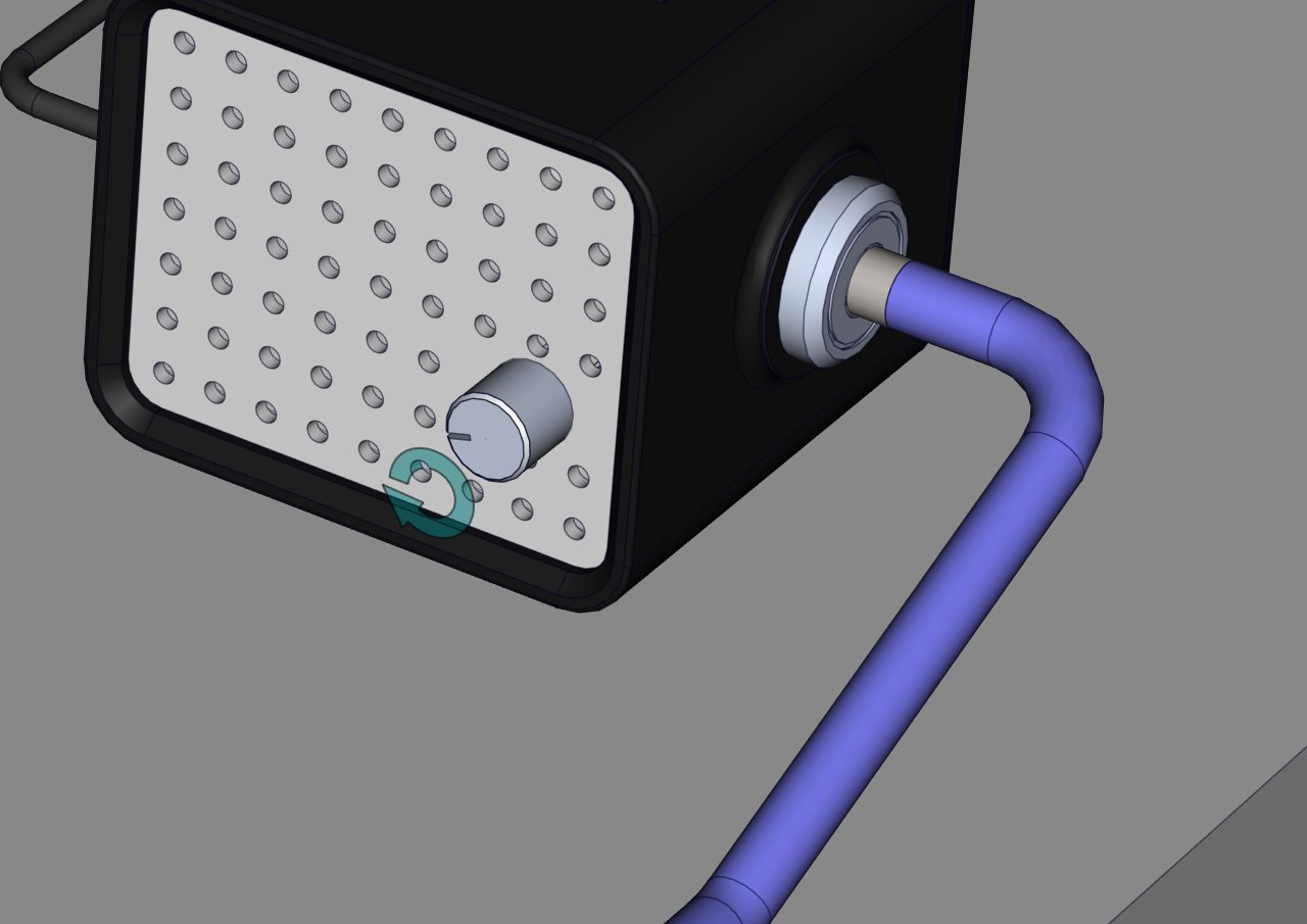
Step 30
When the screen is powered on, you should be able to turn the knob on the front of the light source to activate the light.
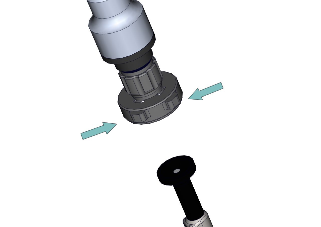
Step 31
Connect the camera coupler to the laparoscope by pinching the two clasps.
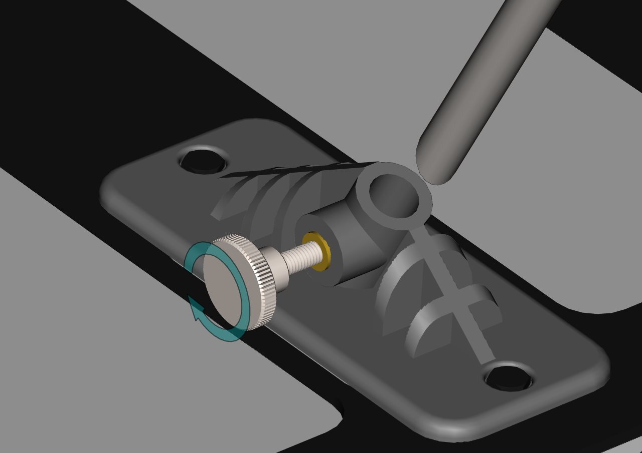
Step 32
Slide the laparoscope into the bracket and lock into position by tightening the thumb screw.
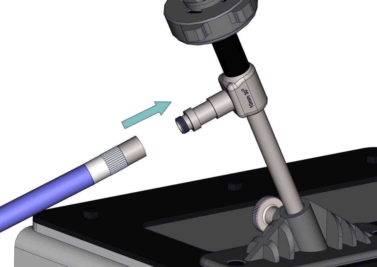
Step 33
Attach the other end of the fibreoptic cable to the connector on the scope by screwing it into place. At this stage, you are ready to turn the light source on.
Step 34
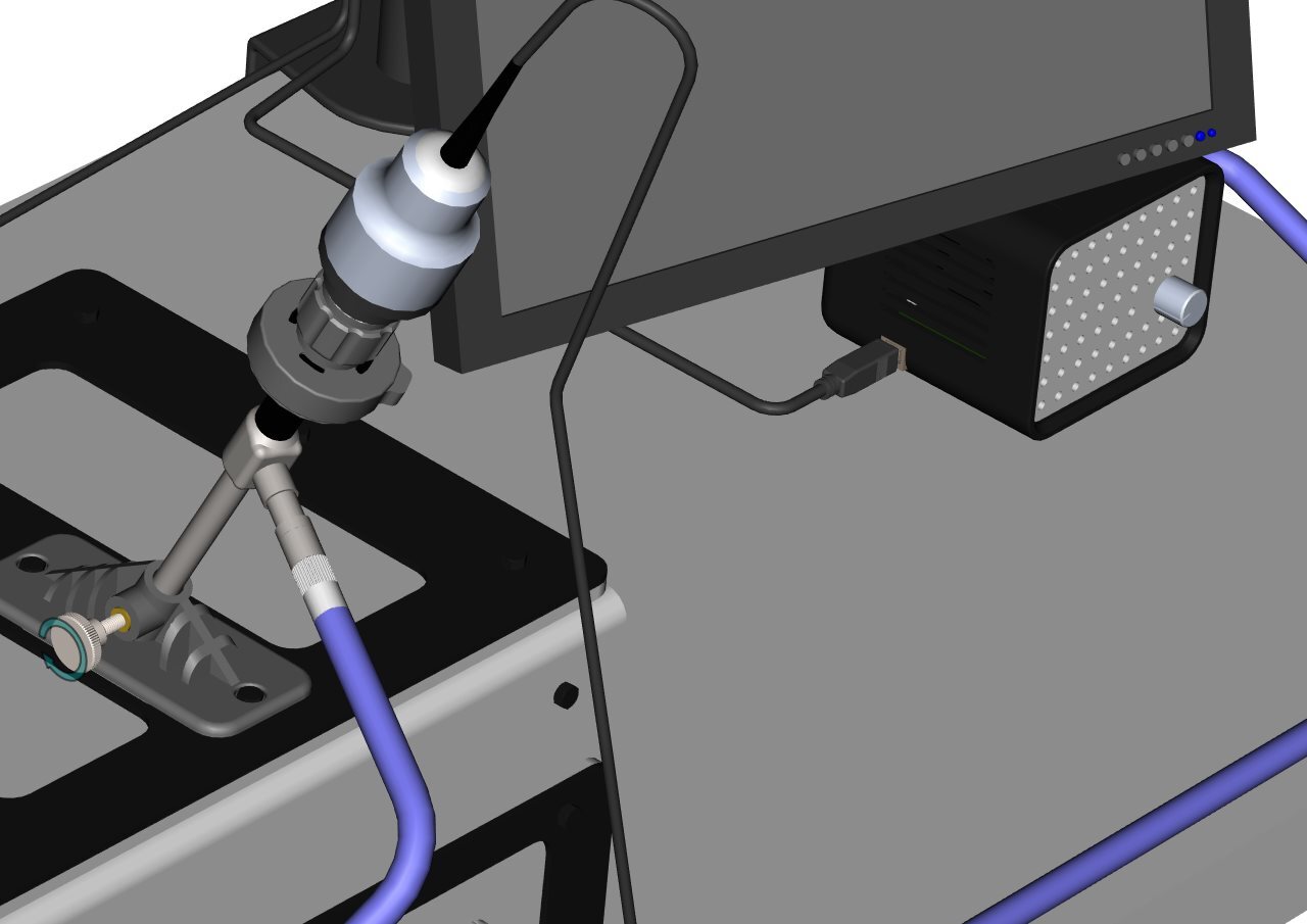
The scope system should look something like this.
Step 35
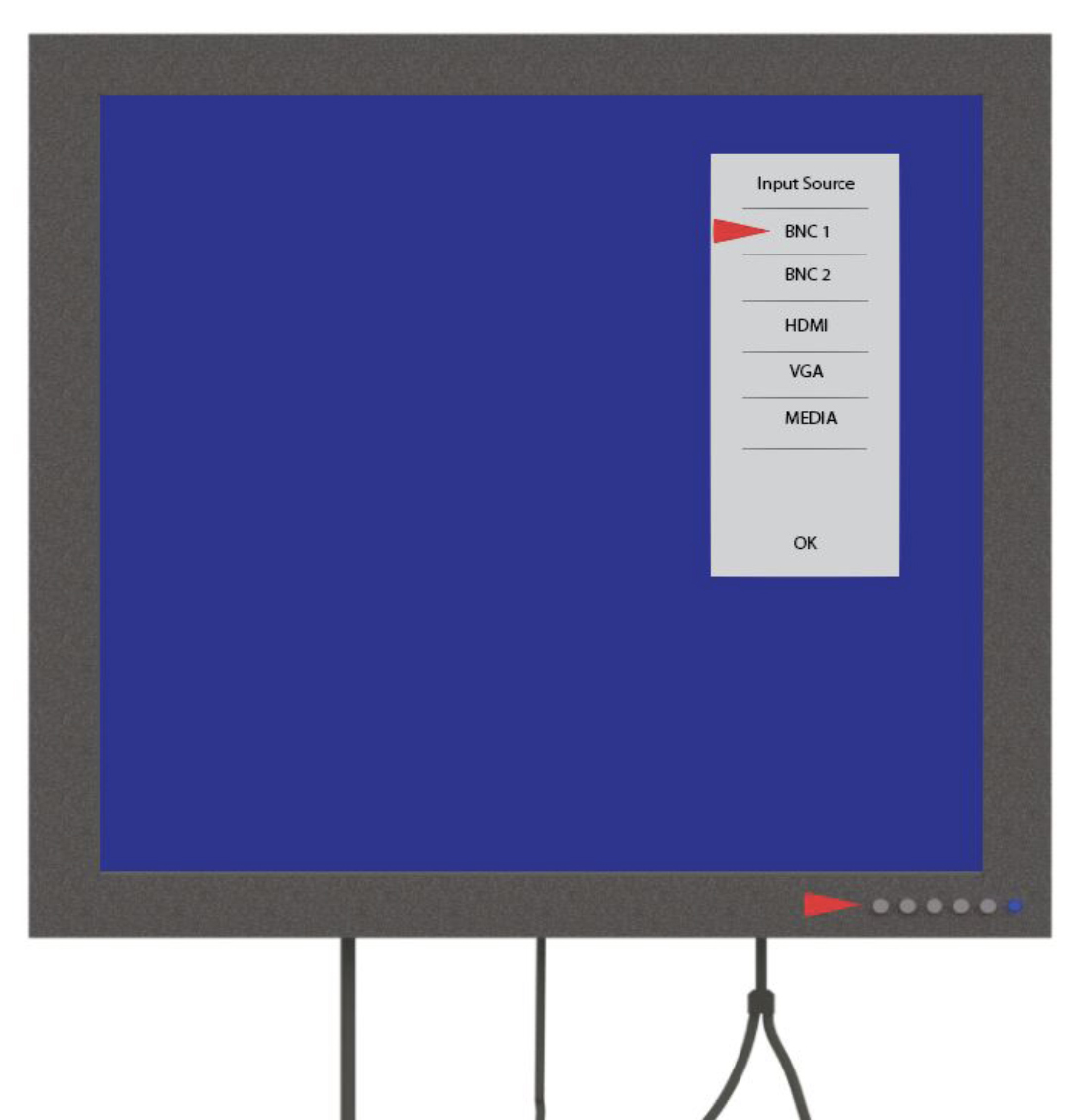
In most cases, your monitor will have been pre-programmed to display the image.
Related articles
Community Discussions (0)
Real-world experiences from other users around this article.
Did this solve your problem?